Purpose of an ER Diagram
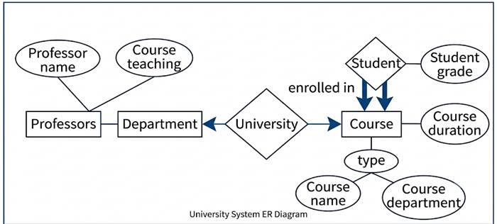
An ER (Entity-Relationship) Diagram is used to visually represent the structure of a database. It shows the entities, their attributes, and the relationships between them, acting as a blueprint before the actual database is implemented.
Main purposes:
- To identify the entities in a system, meaning the main objects or concepts about which data needs to be stored.
- To show the attributes of each entity, meaning the specific properties or details that describe that entity.
- To represent relationships between entities, showing how different entities are connected or associated with each other.
- To help in database design before creating tables, since the ER diagram acts as a conceptual plan that is later converted into relational tables.
- To make the database structure easier to understand, especially for people who are not familiar with SQL or technical database terms.
- To act as a communication tool between database designers, developers and business stakeholders, so everyone agrees on what data is needed and how it is related.
- To identify constraints early, such as cardinality ratios (one to one, one to many, many to many) and participation constraints, before implementation begins.
- To detect design flaws or missing requirements at an early stage, which is much cheaper to fix on paper than after the database has already been built.
- To provide a standard, easy to read notation (rectangles, ovals, diamonds) that makes complex database structures simple to visualize at a glance.