Optical fiber is a modern communication medium that carries information using light instead of electrical signals. Today, almost every phone call, internet video, streaming service, or online transaction travels across an optical fiber at some point. The reason is simple: optical fibers offer extremely high bandwidth, low signal loss over long distances, and immunity to electromagnetic interference.
This answer explains what optical fiber is, how it works, its types and components, the physics behind signal transmission, practical applications, and a balanced discussion of advantages and disadvantages. The aim is to present the ideas in simple and clear language suitable for college students, while maintaining technical accuracy.
What is Optical Fiber?
An optical fiber is a very thin, flexible strand—usually made of glass (silica) or plastic—that guides light from one end to the other. It works on the principle of total internal reflection, which keeps light bouncing inside the fiber core with very little loss. In communication systems, light is used to represent digital information: a light pulse may represent 1, and its absence may represent 0. By sending many pulses quickly, we encode and transmit data at very high speeds.
The wavelength of light commonly used in optical fibers falls in the infrared region (not visible to human eyes), especially around 850 nm, 1310 nm, and 1550 nm. These “windows” have low attenuation (low loss) in silica fibers, making them ideal for long-distance communication.
Structure of an Optical Fiber
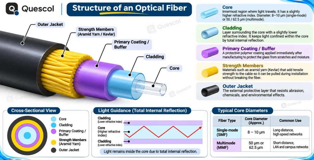
Although an optical fiber looks like a simple strand, it has multiple layers designed for efficient light guidance and mechanical protection.
- Core: The innermost region where light travels. It has a slightly higher refractive index than the surrounding cladding. Typical diameters are about 8–10 micrometers for single-mode fiber and 50 or 62.5 micrometers for multimode fiber.
- Cladding: A layer surrounding the core with a slightly lower refractive index. This difference keeps light confined within the core by total internal reflection.
- Primary coating/buffer: A protective polymer coating applied immediately after manufacturing to protect the glass from scratches and moisture.
- Strength members: Materials such as aramid yarn (Kevlar) that add tensile strength to the cable so it can be pulled during installation without breaking the fiber.
- Outer jacket: The external protective layer that resists abrasion, chemicals, and environmental effects.
Working Principle: Total Internal Reflection
Optical fibers guide light using basic laws of physics—refraction and reflection:
- When light passes from one medium to another (e.g., air to glass), it bends; this is refraction.
- If light inside a denser medium (high refractive index) hits the boundary with a less dense medium (lower refractive index) at a sufficiently large angle, it reflects entirely back into the denser medium; this is total internal reflection (TIR).
Step-by-step explanation of signal transmission:
- Step 1: A transmitter (LED or laser) generates light pulses corresponding to digital bits.
- Step 2: The light enters the fiber core within a specific “acceptance cone.” If the entry angle is within this cone, the light will undergo total internal reflection at the core-cladding boundary and stay trapped in the core.
- Step 3: As light travels along the core, it reflects repeatedly at the core-cladding interface, propagating through the fiber.
- Step 4: At the far end, a photodetector (e.g., a PIN or APD photodiode) converts the arriving light pulses back into electrical signals for further processing.
Two important terms:
- Critical angle: The minimum angle of incidence (measured inside the core) needed for total internal reflection to occur at the core–cladding boundary.
- Numerical Aperture (NA): A measure of how much light the fiber can accept. In simple words, a higher NA means the fiber can capture light entering from a wider range of angles. For step-index fibers, NA is determined by the difference in refractive indices of the core and cladding.
Types of Optical Fibers
Optical fibers can be classified in several ways. The most important categories are by mode of propagation, refractive index profile, and material.
By Mode: Single-Mode vs. Multimode
- Single-Mode Fiber (SMF):
- Has a very small core diameter (about 8–10 micrometers).
- Allows only one propagation path (mode) of light.
- Minimal modal dispersion (very low spreading of pulses).
- Supports very long distances (tens of kilometers per unamplified span, and thousands of kilometers in systems using optical amplifiers or regenerators) and very high data rates.
- Commonly used at 1310 nm and 1550 nm with laser sources.
- Multimode Fiber (MMF):
- Has a larger core (typically 50 or 62.5 micrometers).
- Supports many propagation paths (modes).
- More modal dispersion than single-mode; suitable for shorter distances (tens to hundreds of meters to a few kilometers depending on data rate).
- Commonly used at 850 nm and 1300 nm with LED or VCSEL sources.
By Refractive Index Profile: Step-Index vs. Graded-Index
- Step-Index Fiber: The refractive index of the core is uniform and abruptly changes at the core–cladding boundary. Simple design but higher modal dispersion in multimode versions.
- Graded-Index Fiber: The core’s refractive index decreases gradually from the center towards the cladding. This design reduces modal dispersion because light traveling in higher-order modes (longer paths) passes through regions with lower refractive index and moves faster, compensating for the longer distance.
By Material: Glass vs. Plastic
- Glass (Silica) Fibers: Most common in telecom and data networks. Very low attenuation, high temperature tolerance, suitable for long distances and high speeds.
- Plastic Optical Fiber (POF): Cheaper, thicker cores, easier to handle and terminate, but higher attenuation. Good for short-distance, low-cost applications (e.g., in vehicles, home audio links, or short industrial links).
Light Sources and Detectors
To send and receive information over fiber, we use optoelectronic components.
- Light Sources:
- LED (Light Emitting Diode): Inexpensive, simple, lower power and speed, broader spectrum. Used mainly with multimode fibers for short distances.
- Laser (e.g., Fabry–Perot, DFB, VCSEL): Higher power, narrow spectrum, high speed, long distances. VCSELs are common at 850 nm for multimode; DFB lasers are common at 1310/1550 nm for single-mode and long-haul systems.
- Detectors:
- PIN Photodiode: Converts light into current. Good sensitivity and speed for many applications.
- APD (Avalanche Photodiode): Higher sensitivity due to internal gain but requires higher bias voltage and careful noise management.
Signal Transmission Characteristics
Two main challenges in optical communication are attenuation (loss of signal strength) and dispersion (spreading of pulses). Understanding these is essential for designing efficient links.
Attenuation (Loss)
Attenuation is measured in decibels per kilometer (dB/km). Lower is better. Typical modern single-mode fibers can have losses around 0.2 dB/km at 1550 nm.
- Intrinsic loss:
- Absorption: Due to impurities and the intrinsic properties of glass. Carefully purified silica reduces this significantly.
- Rayleigh scattering: Caused by microscopic variations in the glass structure; dominates at shorter wavelengths.
- Extrinsic loss:
- Bending loss: Tight bends cause light to leak from the core into the cladding. Fibers have a minimum bend radius to avoid this.
- Splice and connector loss: Poor alignment, dirt, or air gaps at joints increase loss.
- Microbending and macrobending: Tiny or large-scale bends or pressure points in the cable can cause additional loss.
Dispersion (Pulse Spreading)
Dispersion broadens the transmitted pulses over distance, which can cause overlap between adjacent bits and lead to errors.
- Modal dispersion: Present in multimode fibers where different modes take different paths and arrive at different times. Graded-index design helps reduce this.
- Chromatic dispersion: Different wavelengths of light travel at slightly different speeds in the fiber. This affects single-mode fibers too. Sources with narrower spectral width (like DFB lasers) reduce this effect. Dispersion-shifted fibers and dispersion compensation modules are used in long-haul systems.
- Polarization Mode Dispersion (PMD): In single-mode fibers, slight asymmetries cause different polarizations to travel at different speeds. PMD is critical in very high-speed long-distance links.
The overall capacity of a fiber link is often described by the bandwidth-distance product. For example, a certain multimode fiber might support 10 Gbps over 300 meters, while single-mode fibers can support much higher data rates over tens of kilometers.
Components and Connections in Fiber Systems
Beyond the fiber itself, a complete system includes connectors, splices, transceivers, and sometimes amplifiers and multiplexers.
- Connectors: Devices that allow fibers to be plugged in and out. Common types include SC (square push-pull), LC (small form factor latch), ST (bayonet), and MPO/MTP (multi-fiber). Cleanliness is crucial; dust or oil can severely increase loss.
- Splices:
- Fusion splice: Ends are precisely aligned and melted together. Very low loss (around 0.05 dB) and high reliability.
- Mechanical splice: Ends are aligned and held by a fixture with gel. Slightly higher loss; faster and cheaper to implement.
- Transceivers: Modules that convert electrical signals to optical and back (e.g., SFP, SFP+, QSFP). They are wavelength-specific and mode-specific.
- WDM (Wavelength Division Multiplexing): Combines multiple wavelengths (colors) of light on the same fiber to increase capacity. Dense WDM (DWDM) can carry dozens to hundreds of channels on one fiber over long distances.
- Optical Amplifiers: EDFA (Erbium-Doped Fiber Amplifier) boosts optical signals at 1550 nm without converting to electrical signals, enabling ultra-long links.
- Passive Optical Networks (PON): Use passive splitters to connect many users to a single fiber from the central office (e.g., GPON, XGS-PON for fiber-to-the-home).
Installation and Handling: A Step-by-Step Overview
Installing optical fiber requires careful planning and precise workmanship.
- Step 1: Planning: Determine link distance, required data rate, fiber type (single-mode or multimode), connector types, and routing path. Consider environmental factors (indoor/outdoor, aerial/buried).
- Step 2: Cable selection: Choose the appropriate cable construction (loose tube for outdoors, tight-buffered for indoors), jacket material (e.g., LSZH for safety indoors), and fiber count.
- Step 3: Installation: Pull or blow the cable through conduits or ducts. Respect the minimum bend radius and maximum pulling tension. Use strength members for pulling; never pull on the bare fiber.
- Step 4: Termination: Terminate fibers with connectors or prepare for splicing. For connectors, the fiber end must be precisely cleaved and polished. For splicing, use a fusion splicer for high-quality joints.
- Step 5: Testing and certification: Measure insertion loss and optical return loss with an optical loss test set (OLTS). Use OTDR (Optical Time Domain Reflectometer) to find faults, measure splice/connector losses, and verify overall link quality.
- Step 6: Documentation and labeling: Label fibers and document routes for maintenance and troubleshooting.
- Safety: Avoid looking into active fibers—infrared light is invisible but can harm eyes. Use protective eyewear during splicing and handle fiber scraps carefully; tiny shards can penetrate skin.
Applications of Optical Fiber
- Telecommunications and Internet backbone: Long-haul submarine cables, national backbones, and metropolitan networks use single-mode fiber with WDM to carry enormous data volumes over thousands of kilometers.
- Fiber to the Home (FTTH): Passive Optical Networks bring high-speed internet, IPTV, and voice services directly to residences.
- Data centers and enterprise networks: High-speed links between switches, servers, and storage use multimode fibers (short-range) and single-mode fibers (longer-range) for 10G/40G/100G and beyond.
- Cable TV (CATV): Fiber distributes TV signals with low loss and high quality across wide areas.
- Medical imaging and surgery: Fiber optics transmit light in endoscopes and minimally invasive surgical tools. Specialty fibers deliver laser energy for treatment.
- Industrial sensing and monitoring: Fiber Bragg Grating (FBG) sensors measure strain, temperature, and pressure in bridges, pipelines, aircraft, and power systems. They are immune to electromagnetic interference and can be multiplexed along a single fiber.
- Military and aerospace: Secure, lightweight cabling that resists electromagnetic pulses and eavesdropping.
- Smart grids and railway signaling: Robust communication for critical infrastructure with high reliability and immunity to interference.
- Lighting and decoration: Plastic fibers for illumination and decorative effects (e.g., star ceilings).
Advantages of Optical Fiber
- Very high bandwidth: Fibers can carry huge amounts of data. With WDM, a single fiber can transport terabits per second.
- Long-distance transmission: Low attenuation reduces the number of repeaters or amplifiers required, lowering costs and latency over long links.
- Immunity to electromagnetic interference: Since light is used, fibers are unaffected by electromagnetic noise, crosstalk, or lightning, making them ideal in noisy industrial environments.
- Security and low signal leakage: It is difficult to tap a fiber without detection. This provides enhanced data security for sensitive communication.
- Small size and light weight: Fibers are thinner and lighter than copper cables, making installation easier in crowded ducts and reducing structural load.
- Electrical isolation and safety: No current flows in fiber; there is no risk of sparks. Useful in explosive environments or where ground potential differences exist.
- Scalability and future-proofing: Existing fibers can support new, higher data rates by upgrading terminal equipment and using advanced modulation/WDM.
- Low total cost at scale: While initial installation can be expensive, the operational costs per bit are low, especially over long distances and high capacities.
- Low latency over long haul: Fewer regenerators and direct optical amplification can reduce processing delays, beneficial for long-distance services.
Disadvantages and Challenges of Optical Fiber
- Higher initial installation cost: Trenching, ducting, splicing, and skilled labor can be expensive, especially in last-mile deployment.
- Fragility and handling sensitivity: The glass fiber is delicate. Excessive bending, crushing, or pulling can cause micro-cracks and signal loss.
- Specialized tools and skills required: Splicing, connectorization, and testing need trained technicians and precise equipment.
- No power delivery: Unlike copper, fiber cannot deliver electrical power to remote devices. Separate power arrangements are required.
- Connector cleanliness: Connectors must be kept very clean; even tiny dust particles can cause significant loss and reflections.
- Repair complexity: Locating and repairing a fault, especially in buried or aerial cables, requires time and specialized tools (e.g., OTDR, splicers).
- Bend sensitivity: Tight bends lead to macrobending losses, and repeated small bends (microbends) can degrade performance over time.
- Temperature and chemical sensitivity (for some cable types): Although glass is stable, coatings and jackets must be chosen carefully for extreme environments.
Comparison with Copper Cables
- Bandwidth: Fiber supports much higher data rates than copper twisted pair or coaxial cables.
- Distance: Fiber can transmit over many kilometers without repeaters, while copper typically supports tens to hundreds of meters at high speeds.
- Interference: Fiber is immune to electromagnetic interference; copper is susceptible to noise and crosstalk.
- Security: Tapping fiber is more difficult; copper can radiate signals that are easier to intercept.
- Size and weight: Fiber cables are thinner and lighter, easing installation.
- Power: Copper can supply power (e.g., Power over Ethernet); fiber cannot, requiring separate power infrastructure.
- Cost: Copper patch cables and terminations are cheaper in very short links. Fiber offers better cost per bit over longer distances and high-capacity needs.
- Durability: Copper is mechanically robust for frequent plugging; fiber connectors and cables need more careful handling.
Key Performance Metrics and Practical Considerations
- Link budget: The sum of all losses (fiber attenuation, splice losses, connector losses) must be less than the transmitter power minus the receiver sensitivity. Designing the link budget ensures reliable operation.
- Optical Return Loss (ORL) and reflections: Excessive reflections can disturb lasers and reduce signal quality. Use angled physical contact (APC) connectors where necessary.
- Bend radius: Follow manufacturer-recommended minimum bend radii (e.g., 10–20 times the cable diameter) to avoid macrobending loss.
- Wavelength choice: 850 nm for short-reach multimode; 1310 nm for metro and legacy systems; 1550 nm for long-haul and DWDM with EDFAs.
- Standards: Ethernet over fiber standards (e.g., 1000BASE-SX/LX, 10GBASE-SR/LR, 100GBASE-LR4), PON standards (GPON, XGS-PON), and ITU-T/IEEE recommendations guide interoperability.
Worked Example: Designing a Simple Campus Fiber Link
Scenario: A university needs a 10 Gbps link between two buildings 2 km apart.
- Choice of fiber: Single-mode fiber is appropriate because 2 km exceeds the comfortable range for most multimode 10G solutions.
- Transceivers: Use 10GBASE-LR transceivers operating near 1310 nm designed for up to 10 km on SMF.
- Link budget estimate:
- Fiber attenuation at 1310 nm: around 0.35 dB/km → about 0.7 dB over 2 km.
- Two connectors (one at each end): assume 0.5 dB total (0.25 dB each).
- One splice in the middle: 0.1 dB.
- Total estimated loss: 0.7 + 0.5 + 0.1 = 1.3 dB.
- Verification: If the transceiver’s power budget (transmit power minus receiver sensitivity) is larger than 1.3 dB, the link will work with margin. Most 10GBASE-LR transceivers have sufficient budget for several kilometers, so this link is safe.
- Installation tips: Use proper cable ducts, observe bend radius, fusion splice for higher quality, and test with OTDR and OLTS.
This simple plan shows how fiber type, wavelength, and loss estimates guide practical design.
Real-World Trends
- 5G/6G backhaul: Small cells require high-capacity fiber backhaul or fronthaul to the core network.
- Massive data center interconnects: Hyperscale operators use single-mode fiber and DWDM across campuses and metro regions.
- FTTH expansion: Governments and ISPs are investing in fiber to reduce the digital divide and support remote education and work.
- Advanced modulation: Coherent optics and sophisticated coding increase spectral efficiency on long-haul networks.
- Sensing with standard cables: Distributed Acoustic Sensing (DAS) and Distributed Temperature Sensing (DTS) turn regular fibers into long, continuous sensors for security and infrastructure monitoring.
Conclusion
Optical fiber forms the foundation of modern communication networks, transmitting data as light through strands of glass or plastic using total internal reflection. With components like lasers, photodiodes, amplifiers, and WDM technology, it enables ultra-high-speed, long-distance communication. Single-mode and multimode fibers cater to different applications—from backbone links to local networks. Though installation requires precision and investment, fiber offers unmatched bandwidth, low signal loss, and immunity to interference. Its scalability and reliability make it indispensable for telecom, internet, and data center infrastructure, driving the world’s high-speed connectivity.